

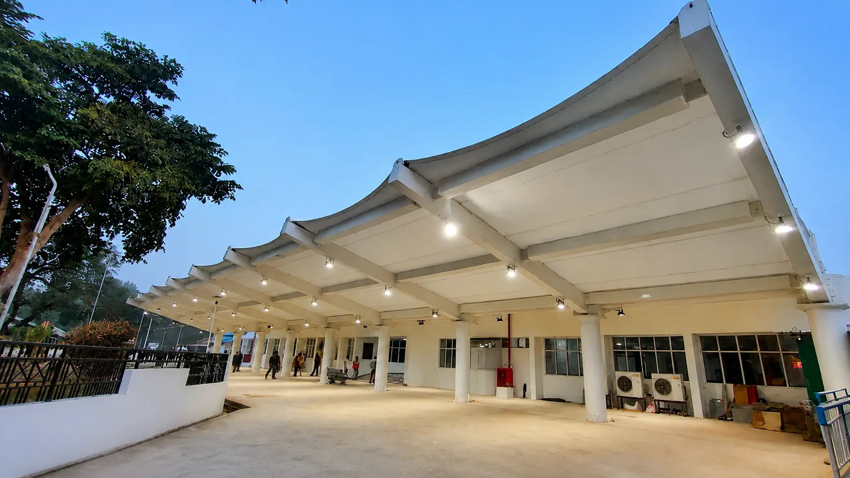
Tensile Structure Design, Engineering & Fabrication
The shape is the structure, the patterning decides whether it fits, and the seam decides how long it stays watertight. All three are engineering decisions, which is why Ekra Decor keeps design, membrane fabrication, steel fabrication and installation in one accountable chain rather than buying them in.
Engineering and making cannot be separated on a tensile structure
On a beam-and-column building the design and the fabrication are two jobs. On a tensioned membrane they are the same job, because the shape is what carries the load.
A tensile roof has no stiffness of its own. It gets its strength from double curvature and pre-stress, so the geometry is not styling — it is the structure. That has a practical consequence: the drawing office, the patterning table, the welding bay and the tensioning crew are all working on the same structural decision at different stages, and an error in any one of them only becomes visible at the next.
Patterning that is compensated wrongly produces panels that will not come up to tension. A seam welded wrongly holds for a season and then opens. A frame drilled on site instead of in the shop leaves bare steel at the connection. None of these are visible at the stage where they are made, which is the argument for keeping all of them under one roof. Ekra Decor is both the designer and the tensile structure fabricator on its own projects, and subcontracts none of it. What we take on commercially, and where the line between our scope and yours is drawn, is set out on the tensile structure contractor page; this page is the method behind it.
Tensile structure form finding, load analysis and structural analysis
The shape is generated, not chosen. Everything downstream — membrane grade, cable sizes, steel sections, foundation loads — is an output of that step.
Form finding generates the equilibrium surface for a given set of supports, edges and pre-stress. The result is an anticlastic surface that carries both downward load and uplift and drains to its low points. Only once that surface exists is there anything meaningful to analyse, which is why a catalogue shape scaled to fit a different span is not the same product.
Form finding and analysis are run in ixCube and ANSYS. The analysis checks the found shape against wind, and against rain or snow where the location calls for it. Membrane stresses, cable forces and steel sections are results of that run.
Form finding
The equilibrium shape for the supports, edges and pre-stress specified — an anticlastic surface that resists uplift as well as downward load and drains to designed low points.
Structural analysis
The found shape analysed in ixCube and ANSYS for wind, and for rain or snow where relevant. Membrane stress, cable force and steel section all come out of this step.
Wind load design
Wind to IS 875 Part 3, using the figure for your site after terrain, height and topography factors. Our 150 km/h basis is a floor that gets raised when the site figure is higher — see wind load on a tensile structure.
Cable and edge design
Boundary and ridge cable forces sized from the analysis, with the hardware that transfers them into the frame detailed rather than assumed.
Structural steel design
Masts, arches and frames to IS 800, sized for the span and the wind rather than for the look of the sketch.
Foundations
Footings to IS 456, checked for uplift and overturning — the governing case on a large light roof is usually wind lifting it, not weight pushing down. See foundation design.
Design pressures, membrane stresses, cable forces and deflections are project-specific and come out of the analysis for your site. They are issued as drawings and figures before anything is cut, and we do not publish representative values here, because a generic number on a web page is not a design.
3D modelling, CAD and the drawings you actually receive
Before anything is detailed there is a 3D render and a walk-through of the geometry for sign-off, so the form is agreed while changing it is still cheap. After that the model becomes two sets of drawings: general-arrangement and workshop drawings for the steel, and the developed membrane surface for the cutting floor.
Which drawings you get, and when, is worth settling in the quotation rather than afterwards — it is one of the questions to ask before signing. Where a municipal or authority submission is needed, drawings are prepared in the form the approving authority expects.
3D membrane model
The form-found surface as a 3D model, used for the client walk-through and then as the source for both the steel drawings and the patterning.
CAD and shop drawings
General-arrangement drawings, workshop drawings for fabrication, and good-for-construction drawings in the form the client, consultant or authority needs.
Handover documentation
The design calculations and an operation and maintenance manual at handover, so the structure can be inspected and maintained against what was actually designed.
Patterning and compensation: turning a curved surface into flat cloth
This is the step that decides whether a roof fits, and it is the one with the least margin for error.
A doubly-curved surface cannot be flattened without distortion. So the surface is developed into narrow strips that each flatten with an acceptable error, and the strip width is limited by the width of the fabric roll — the roll dictates the panel layout, not the other way round.
Each flat panel is then cut slightly smaller than its geometric size, because the fabric stretches to shape when it is tensioned. That allowance is the compensation, and the values come from biaxial tests on the specific fabric being used, because warp and weft stretch by different amounts. Compensation is material-specific: it cannot be carried over from one fabric to another, which is why the membrane grade has to be fixed before patterning starts, not after.
In the workshop: cutting, welding and galvanising
Almost everything is made off site. Site work reduces to foundations, erection and tensioning.
Membrane panels are plotted and cut on a CNC table, each marked with its panel number, orientation and seam allowances. The warp direction is aligned consistently across the roof, because the two fabric directions do not behave alike under load.
Seaming follows the material rather than a house preference:
| Material | Seam method | Note |
|---|---|---|
| PVC-coated polyester | High-frequency or hot-wedge welding | Fast and well understood |
| PVDF-lacquered PVC | High-frequency or hot-wedge welding | The lacquer is removed along the seam line first, or a weldable grade is specified |
| PTFE-coated glass | Heat and pressure | Slower and more skilled; the glass base is brittle |
| ETFE film | Thermal film welding | Film, not coated fabric — a different discipline |
| HDPE shade mesh | Sewn or clamped | Not weldable |
A correct weld is as strong as the parent material, which is why the seam is welded rather than stitched or bonded — the longer argument is in how a tensile structure actually gets built.
CNC fabric cutting
Panels plotted and cut on a CNC table, each labelled with panel number, orientation and seam allowance so the roof can only be assembled the way it was patterned.
High-frequency welding
Coatings fused into a continuous seam. The weld, not the open fabric field, is what decides how long the roof stays watertight.
Edge and corner reinforcement
A keder rope or webbing belt welded into the perimeter hem to carry the edge force into the boundary cable or clamped edge; corner plates, extra plies and steel fittings built up where several forces meet.
Steel fabrication
Sections CNC-profiled, cut, welded to procedure and drilled in the workshop — including every hole, so nothing has to be drilled at a connection on site.
Hot-dip galvanising
Corrosion protection to IS 4759 and IS 2629, done after fabrication so cut edges and welds are coated too.
Packing for site
PVC and PVDF folded; PTFE-glass and ETFE rolled on wide cores to avoid creasing a brittle base or a film. Each pack is labelled with its installation sequence.
What gets checked before a panel leaves the shop
Three checks, all of them before the panel is packed, because a fabrication error found on site is a crane, a crew and a programme standing still: weld strength on samples, panel dimensions against the patterning, and hardware and hems against the drawings. Defects are corrected in the workshop rather than adjusted for during installation.
This is also where material substitution would show up. Membrane is specified by grade and finish, and the certifications and registrations behind the company are listed on the certifications page.
Foundations, erection, and bringing the membrane up to pre-stress
The sequence on site is short by design, but it is not flexible.
Foundations come first: excavation, reinforcement, casting, and then curing — the one part of the programme nobody can compress, whatever the pressure on the date. Because the steel arrives already fabricated and galvanised, erection itself is quick: stand the frame, align it, check the levels.
The membrane is then lifted, drawn out, connected to the edge cables and fittings, and brought up to its engineered pre-stress in a controlled sequence. That last step is what turns a slack sheet into a stiff structural surface, and it is done by the crew that fabricated it, to a method statement rather than by feel. Realistic durations are set out in how long a tensile structure takes.
Tensile structure project management: one accountable chain
Survey, engineering, drawings, fabrication, installation and tensioning are run by one in-house team, so there is no hand-off point at which responsibility becomes arguable. Site survey and wind-load analysis, 3D CAD membrane form finding and patterning in ixCube and ANSYS, high-frequency fabric welding, structural steel fabrication and on-site tensioning are all ours.
On the client side, the single most useful thing for the programme is a nominated person who can approve drawings. Fabrication cannot start until drawings are approved, so an approval sitting with an unnamed committee is the most common cause of a date slipping — more common than anything that happens in the workshop.
Tensile structure engineering & fabrication FAQ
How the design, the workshop and the site crew actually work.
Form finding and structural analysis are run in ixCube and ANSYS. Form finding generates the equilibrium shape for the given supports, edges and pre-stress; the analysis then checks that shape for wind, and for rain or snow where relevant. Membrane stresses, cable forces and steel sections are outputs of that step rather than assumptions made before it.
Structural steel to IS 800, foundations to IS 456, wind loading to IS 875 Part 3, and galvanising to IS 4759 and IS 2629. Our standard wind design basis is 150 km/h, checked against the figure IS 875 Part 3 gives for your specific site after terrain, height and topography factors, and raised wherever that is higher. A baseline sets a floor; it does not replace the site calculation.
A doubly-curved surface cannot be flattened without distortion, so it is developed into narrow flat strips that each flatten with acceptable error, with panel width limited by the fabric roll width. Compensation then cuts each panel slightly smaller than its geometric size, because the fabric stretches to shape when it is tensioned. The values come from biaxial tests on the specific fabric, since warp and weft stretch differently. Get compensation wrong and the roof either will not come up to tension or will not fit at all.
Panels are plotted and cut on a CNC table, each marked with its panel number, orientation and seam allowances. Orientation is not cosmetic: the warp direction is aligned consistently across the roof, because warp and weft behave differently under load.
Panels are welded, not stitched or bonded. A stitched seam puts holes through the coating and relies on thread that weathers faster than the fabric. The method follows the material: PVC and PVDF by high-frequency or hot-wedge welding, with the PVDF lacquer removed along the seam line first; PTFE-glass by heat and pressure, which is slower and more skilled; ETFE by thermal film welding. HDPE mesh is sewn or clamped rather than welded. A correct weld is as strong as the parent material.
Yes. Steel is CNC-profiled, cut, welded to procedure, drilled and hot-dip galvanised in the workshop before it reaches site. Drilling in the shop matters more than it sounds: a hole drilled on site because something did not line up leaves bare steel at a connection, which is where corrosion starts.
Weld strength on samples, panel dimensions against the patterning, and hardware and hems against the drawings. Defects are corrected before the panel is packed. Packing is part of the method too: PVC and PVDF are folded, while PTFE-glass and ETFE are rolled on wide cores to avoid creasing a brittle base or a film, and each pack is labelled with its installation sequence.
Most of the work happens off site, which is what keeps site time short. On site the sequence is foundations, erection, then tensioning. The foundations are the one part of the programme nobody can compress, because concrete has to cure. Once the finished steel arrives, erection is quick: stand the frame, align it, check the levels. The membrane is then drawn out, connected to the edge cables and fittings, and brought up to its engineered pre-stress in a controlled sequence.
No stage is subcontracted. Site survey, wind-load analysis, 3D CAD form finding and patterning, high-frequency membrane welding, structural steel fabrication and on-site tensioning are all run by one in-house team. That is a quality argument as much as a commercial one, because patterning, welding and tensioning are the three steps where an error only shows up at the next stage.
A handover pack with the design calculations and an operation and maintenance manual, plus the warranty: one year on the structure and five to fifteen years on the membrane depending on the grade specified. An annual maintenance contract is optional.
Let’s Build Your Structure
Speak directly with our structural engineering team to discuss your project dimensions, material options, or to schedule a free on-site technical inspection across India.
- 28+Years experience
- Pan-IndiaTurnkey execution
- ISO9001:2015 certified
Request an itemised price quote
Fill in your requirements below for a free engineering assessment & itemised estimate.
* required — everything else is optional
Your details are used only to respond to this enquiry.
Chat with an Engineer on WhatsApp