

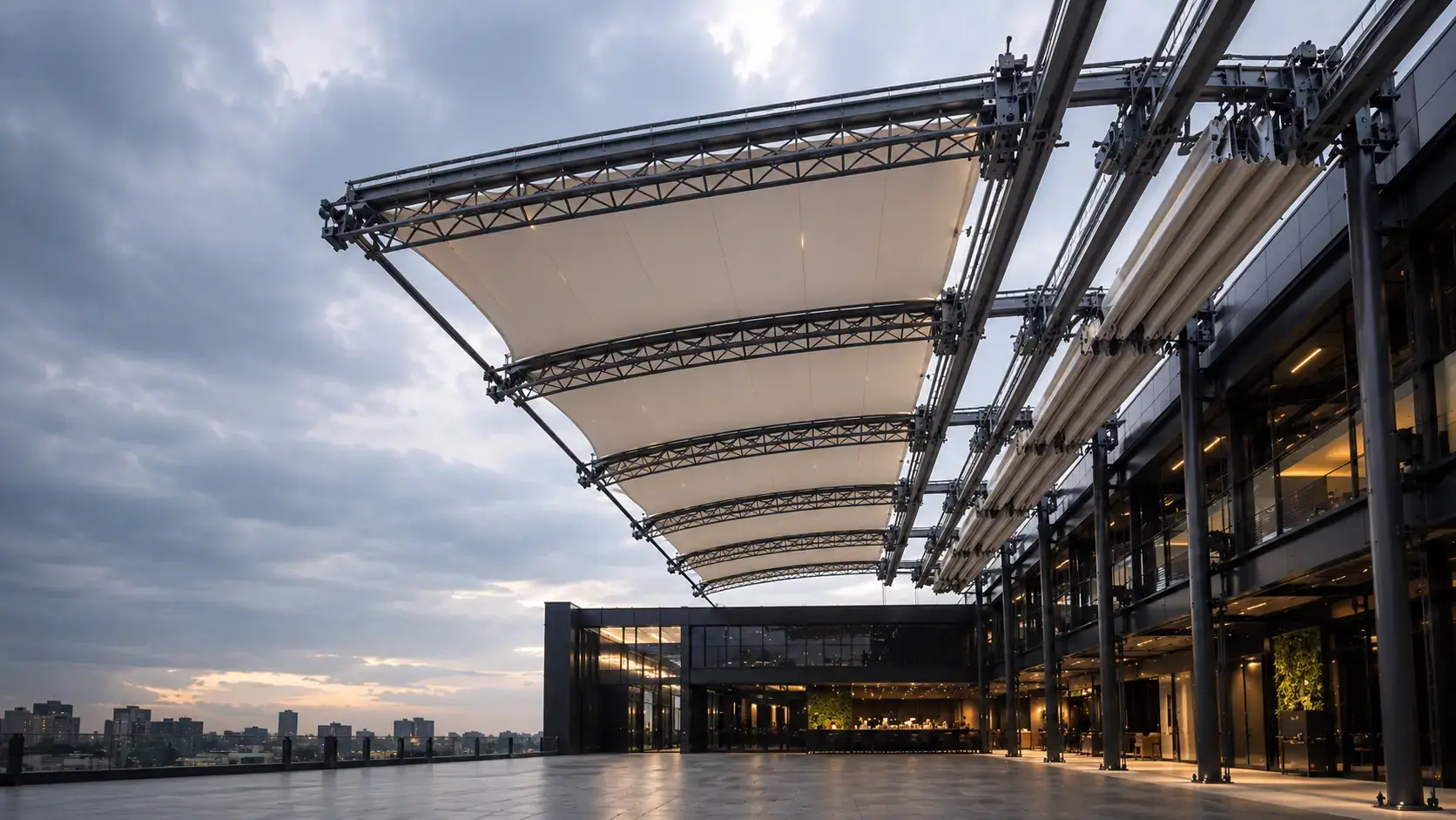
Retractable Roof Systems Manufacturer
Engineered retractable roofing systems designed to transform large-span spaces between covered and open-air environments — the primary steel structure stays fixed; only the membrane bays travel.
Reviewed by Mukesh Mittal, Senior Structural Engineer · Last updated: 14 September 2026
A Roof That Adapts
to the Space
A retractable roof system lets a large space operate as a protected indoor environment or an open-air environment, depending on operational requirements and the weather.
The fixed elements — foundations, columns and the primary steel frame — carry every load at all times. The membrane-carrying roof bays are the only part that moves, travelling along a fixed guide system between positions.
How a Retractable Roof Works
One structure, three states. The membrane bays travel along the eave guide rail and stack at the parking end; the primary structure never moves.
Closed
Membrane sections provide full overhead coverage across the opening.
Partial
Moving roof sections retract along the guide system toward the parking end.
Open
The roof sections are positioned clear of the opening; the floor is open to the sky.
Twelve Systems, One Load Path
Every component of a large-span retractable roof, from the membrane surface down to bearing ground. Select a component to highlight it.
Component set shown where applicable to this membrane and frame type. The confirmed configuration and hardware for any project are issued at detailed engineering and shop-drawing stage.
One Continuous
Load Path
Every load on the roof — self-weight, wind, and the mechanical forces of retraction — follows one uninterrupted path from the membrane surface down to bearing ground. The retractable bays introduce a single moving link, the rail and carriage; every other stage behaves as a conventional fixed-steel load path.
- MembraneSurface load and wind pressure
- Moving frameCollects each bay's load
- Guide rail & carriageThe one moving link in the path
- Primary steelEave trusses and bracing
- ColumnVertical and lateral transfer
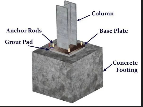
- Base plate & anchor rodsLoad spread and hold-down
- RCC foundationInto the ground-bearing strata
Final structural dimensions, connections and foundation design are determined through project-specific engineering calculations and site conditions.
Precision Behind
Every Movement
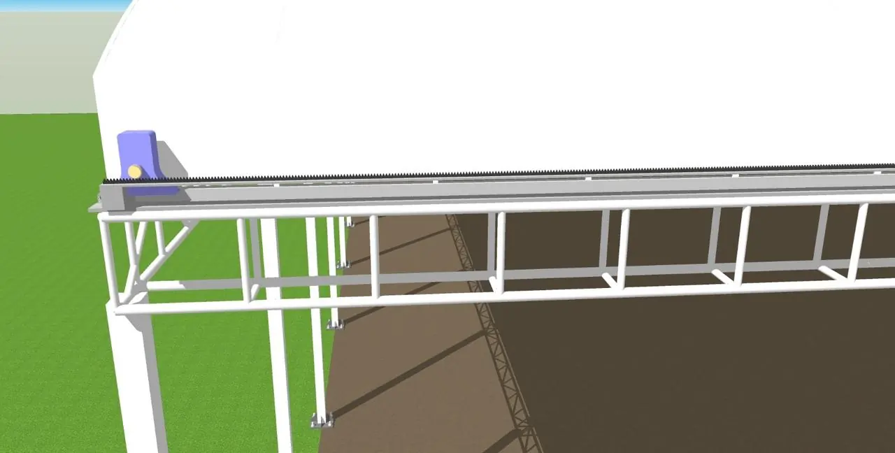
The movement system is engineered to guide the retractable roof sections along their designed travel path — a motorised carriage per bay, engaging the fixed rail, with travel synchronised across all moving bays.
The Frame Carries
Everything
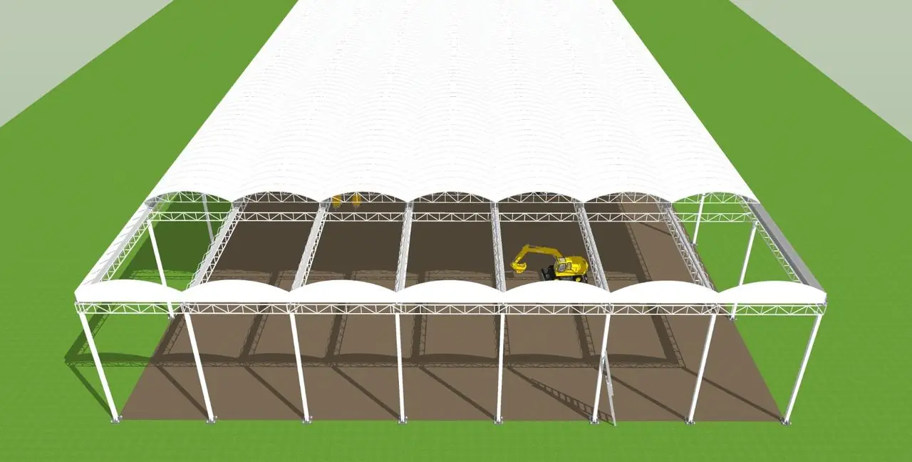
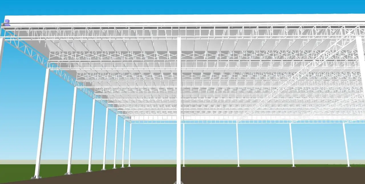
The fixed steel skeleton — columns, eave trusses and rafter framing — carries the entire roof, moving and stationary, down to the foundations. Bracing and connection plates tie every member into one continuous, laterally stable frame.
Primary steel
Columns, eave lattice trusses and main cross-bracing — sized for the span, the wind zone and the connections.
Secondary members
Rafter framing and purlins between the primary trusses, supporting the membrane bays.
Bracing
Ties the frame into one laterally stable structure against wind and the forces of retraction.
Moving frame & rails
The retractable sub-frames and the eave-mounted guide rails they travel on — the only elements that move.
Structural coordination, member sizes, load transfer and connection design are established through project-specific engineering against the site and the applicable codes — not assumed at concept stage.
The Membrane Is
Part of the Engineering
Material selection is not a finish choice made at the end — it is set by the span, the retractability, and the environment the roof has to work in.
PVC-coated polyester
Economical, widely used, and workable for retractable panels that must pleat and re-tension. PVC membrane →
PVDF-coated membrane
A PVC base with a PVDF surface treatment — enhanced durability, better self-cleaning, a longer surface life. PVDF finish →
PTFE-coated fibreglass
High durability, high translucency and a long service life — where the project justifies it. PTFE membrane →
ETFE systems
A foil-based envelope, used where project requirements justify it rather than a woven membrane. ETFE film →
The right material for a retractable roof depends on span, retractability, durability, UV exposure, translucency, fire performance, environmental conditions, maintenance and architectural requirements. It is not the case that every material applies to every retractable roof. See the full membrane material guide and how long each membrane lasts.
Where the Fabric
Meets the Frame
Each fabric panel terminates at the moving frame line through a build-up of components that carry the tension and keep the joint watertight.
- Membrane edgeThe fabric panel terminates at the moving frame line
- Edge reinforcementA reinforced fabric strip or webbing along the termination edge
- Edge cable / tensioning componentMaintains fabric tension along the edge run
- Clamp / profileAn aluminium or steel clamp plate securing the edge
- FastenersMechanical fixings through the clamp into the structural member
- Steel / moving frameThe retractable rafter or cross-member carrying the bay
Water Follows the Geometry
The barrel-vault bay curvature sheds rainwater toward the eave and valley lines, where it is collected and carried clear of the structure and the floor below — in every roof position, closed or open.
Roof geometry and the drainage layout are coordinated at detailed design stage so water does not accumulate on the roof in any position. Design also considers wind, rain, environmental exposure and operational conditions — the specific figures are established by project engineering, not assumed.
Commanded and Monitored
A deliberate command from an operator initiates movement; safety logic and monitoring sit between that command and the drive at all times.
- OperatorLocal or centralised command interface
- Control systemControl panel and operator logic
- Safety logicInterlocks and permissives checked first
- Motor controlMotor controllers per bay
- Drive systemSynchronised travel across bays
- Retractable roofMonitored movement to position
Control panel & motor controller
The operator interface and the per-bay drive controllers.
Limit switches & position sensors
Define the open and closed travel limits and confirm each bay's location on the rail.
Emergency stop & safety interlocks
Immediate halt from any station; prevention of conflicting or unsafe commands.
Weather sensors
Wind- or rain-triggered response, where specified for the project.
Designed Around
Controlled Movement
Emergency stop
Immediate halt of roof travel from any operator station, at any point in the cycle.
Limit switches
Automatically stop travel at the defined open and closed positions.
Mechanical end stops
A physical backup limiting carriage travel beyond the designed range.
Motor protection
Monitors drive load and halts operation outside safe operating parameters.
Safety interlocks
Prevent simultaneous or conflicting commands across the drive system.
Position monitoring
Synchronised, monitored travel across all retractable bays.
The final safety architecture — device selection, redundancy and interlock logic — is project-specific and confirmed during detailed engineering and the automation design.
Where Large-Span
Retractable Roofs Fit
Wherever one venue has to work as both a covered and an open-air space. Suitability for any specific project is confirmed through structural, mechanical and code review.
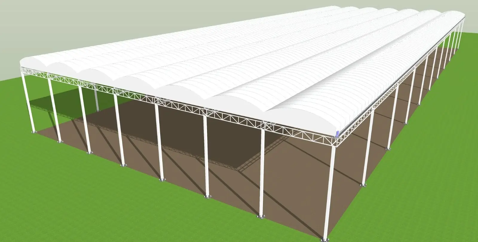
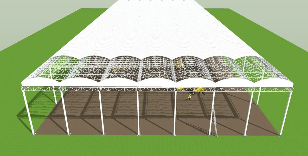
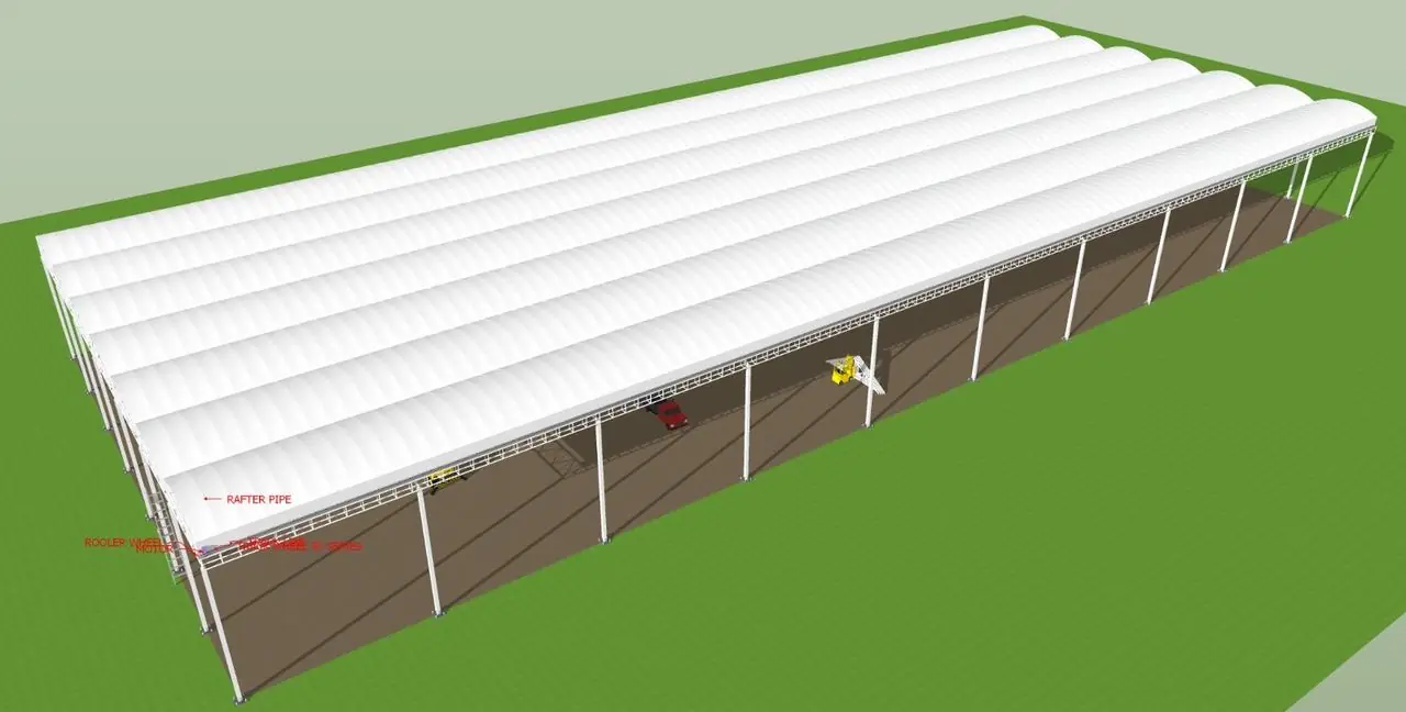
Also suited to public spaces and entertainment venues. All images are 3D design models illustrating the system type — not photographs of completed projects.
Two Decisions That Come First
The system described on this page is motorised and large-span. Two questions sit earlier than any of the engineering above — how the roof is driven, and what the moving panel is made of. Both are worked through in detail separately.
One Venue,
Every Condition
Flexibility
Switch between covered and open-air operation on command.
Weather Adaptability
Provide overhead protection when it is required, and open up when it is not.
Architectural Impact
Create a distinctive large-span architectural roof, not a utilitarian cover.
Space Utilisation
Allow one venue to support multiple operating conditions across the year.
From Concept
to Commissioning
Every discipline a retractable roof needs — structural steel, membrane and mechanical — delivered under one accountable team, practised since 1998.
Site Study
Concept Design
3D Modelling
Structural Engineering
Steel Fabrication
Membrane Fabrication
Mechanical System
Installation
Testing
Commissioning
After-Sales Support
Retractable Roofs, Moving
Short clips of retractable systems in operation. Stills do not show the thing that matters most about a moving roof — whether the membrane stays taut through the whole travel.
Louvre roofs — the hard-roof alternative
These are aluminium louvre systems, not fabric membranes. Included because clients comparing options usually want to see both.
All 16 videos — projects, installation and retractable roofs
The System, in Detail
3D structural design models of a large-span retractable membrane roof — illustrative of the system geometry and its component detail. Not photographs of completed projects.
Structure
Mechanism & Detail
Retractable Roof — Questions
A retractable roof is a permanent steel structure carrying a moving fabric envelope. Motorised roof sections travel along a fixed guide system, allowing a covered floor to transition, on command, between a weather-protected enclosure and an open-air space — without dismantling any part of the primary structure.
Each membrane bay is carried on a light steel moving frame with roller-wheel carriages at each end that engage a fixed guide rail on the eave truss. A motorised drive per bay moves it along the rail, with travel synchronised and monitored across all bays. The bays stack at a parking end when the roof is open; the primary structure never moves.
PVC-coated polyester, PVDF-coated membrane, PTFE-coated fibreglass, and ETFE foil systems where appropriate. The choice is set by the span, the retractability, durability, UV exposure, translucency, fire performance, the environment, maintenance and the architectural requirement — it is not the case that every material suits every retractable roof.
Yes. At building and stadium scale the roof is a permanent steel frame on a perimeter column grid carrying motorised membrane bays. The clear span, bay count, structural sizes and foundation design are all established by project-specific engineering against the site and the applicable codes.
Through a control panel and per-bay motor controllers, with limit switches and position sensors defining and confirming travel, an emergency stop at every operator station, and safety interlocks preventing conflicting commands. Weather sensors that trigger a wind- or rain-response can be added where specified.
Project requirements and site conditions, structural calculations, wind and rain loading, the operational requirements of the roof, the applicable standards and codes, the material specification, and the mechanical and electrical-safety requirements. These are confirmed at detailed engineering rather than assumed at concept stage.
Periodic cleaning, visual inspection, and inspection of the seams, edges and tension across all bays — alongside inspection and lubrication of the rails, rollers, bearings and drive system, and testing of the control panel, sensors and emergency systems. Ekra Decor provides a maintenance schedule with every project.
It is project-specific — a function of the span, the number of bays, the steel tonnage and the mechanical scope. On-site work is planned around a pre-fabricated steel frame and pre-fabricated membrane panels to keep the sequence efficient; the programme is confirmed once the project is engineered.
Planning a Retractable Roof Project?
Share your project requirements with our team for a concept discussion and a project-specific solution — structure, mechanism, membrane and controls, from one team.
Let’s Build Your Structure
Speak directly with our structural engineering team to discuss your project dimensions, material options, or to schedule a free on-site technical inspection across India.
- 28+Years experience
- Pan-IndiaTurnkey execution
- ISO9001:2015 certified
Request an itemised price quote
Fill in your requirements below for a free engineering assessment & itemised estimate.
* required — everything else is optional
Your details are used only to respond to this enquiry.
Chat with an Engineer on WhatsApp