

Tensile Structure Foundation Design
A membrane roof weighs almost nothing, which is exactly why its footings are bigger than you expect. What sizes them, what the design has to contain, and what to ask for before anyone pours concrete.
Why uplift governs, not weight
A conventional roof is held up. A tensile roof is held down. Almost everything that surprises people about these foundations follows from that one inversion.
A concrete slab resists wind lifting it by being heavy. It has mass to spare, so uplift is rarely the case that sizes anything. A tensioned membrane has no mass to spare at all — the roof is fabric, cable and slender steel, and the wind can generate more pull than the structure weighs.
If the roof cannot hold itself down, something else must, and that something is the foundation. So the footings under a tensile structure are designed against uplift and overturning rather than gravity, and they are sized by the wind case rather than by the weight above them.
This is why the lighter and more elegant the canopy, the harder the footings have to work. People look at a delicate roof, then at the excavation underneath it, and assume someone is over-engineering. The opposite is true: there is less roof to resist the pull, so more of the job falls to the concrete.
What actually sizes a footing
Two numbers decide it, and a quotation that contains neither has not designed a foundation.
The first is the design wind pressure. It comes from the basic wind speed for the specific location under IS 875 (Part 3), adjusted for terrain, height and the importance of the structure. It is not a round number chosen because it sounds reassuring. Our standard design basis is 150 km/h, checked against the site's own figure.
The second is what the ground can do. An isolated footing resists uplift in two ways: through its own mass, and through the weight of the soil sitting on top of it. Both are calculated, and the footing is sized so the total comfortably exceeds the pull the wind can generate, with a margin.
Footings are then designed to IS 456, the frame above them to IS 800, and the steelwork protected by galvanising to IS 4759 / IS 2629. Those four codes are what “engineered” means on a structure like this.
Dead load
The weight of membrane, cables and steel. On a tensile roof this is small, which is the whole problem.
Pre-stress
The membrane is tensioned into shape, and that tension is permanently pulling on the frame and the footings.
Wind uplift
The governing case. Pressure and suction from IS 875 Part 3 for the site, not a generic figure.
Overturning
A cantilever hangs the whole roof off one line of columns, so the footing resists a moment as well as a pull.
Soil above
The weight of earth on top of the footing counts towards holding it down, and is calculated, not assumed.
Rain and snow
Downward cases still have to be checked, and in the hills snow can govern locally.
Footing types, and when each is used
Which one you get is decided by the loads and the ground, not by preference.
| Type | How it holds down | Typically used when |
|---|---|---|
| Isolated pad | Mass of the pad plus the soil bearing on it | The common case — one column, one footing, reasonable ground |
| Raft | A single slab spreading load across a wider area | Weaker or variable soil, or columns close enough to share one base |
| Pile | Friction and end bearing down to competent strata | Soft or filled ground where a pad would need to be impractically large |
| Mass / anchor block | Sheer weight of concrete resisting a cable pull | Where stay or anchor cables come down to ground away from the frame |
| Ballast | Weight resting on the surface, no excavation | Demountable and temporary structures only — see portable fabric structures |
Form matters here too. A cantilever carries the entire roof on one line of columns, so each footing takes a moment as well as a vertical pull and is heavier than the equivalent under a structure supported on both sides. A conical with a single central mast concentrates everything into one base — which can be an advantage when the rest of the area must stay clear.
The soil assumption, and why it has to be written down
The same canopy needs a different footing in dense clay and in loose fill. Any quotation offering one footing size regardless of site has not looked at the site.
A footing design is only as good as the assumption it was based on. Ground that looks identical across two plots can behave very differently, and the difference changes the excavation, the concrete volume and the price.
This is why the soil assumption belongs in writing alongside the design. If the structure is later found to be sitting on made ground or fill that nobody tested, the design was never valid — and by then it is under concrete, where nobody can inspect it without breaking it out.
Where ground conditions are genuinely unknown or suspect, a soil investigation is the cheap step. The expensive step is discovering the problem after the frame is up.
The column base: bolts, grout and pedestal
The foundation does not end at the top of the concrete. The joint between steel and concrete is where uplift is actually transferred, and it is the part that can be inspected later.
Anchor bolts
Cast in, to a layout that matches the base plate. Their embedment is part of the uplift calculation, not an afterthought.
Chemical anchors
Used where fixing into existing concrete is unavoidable, and only where the existing element has been checked for the pull.
Base plate
Sized and stiffened for the moment as well as the tension, and drilled in the workshop rather than on site.
Grout
Packs the gap and transfers bearing evenly. Hollow or cracked grout concentrates load on a few bolts.
Pedestal
Lifts the base plate clear of standing water, which is where corrosion starts on an otherwise sound structure.
Drainage
Water that collects at a column base will find the bolts. Where it goes is a design decision.
These are also the items on the maintenance checklist: movement, cracking around the pedestal, grout condition and anchor-bolt tightness. They are the only part of the foundation you can still see once the job is finished.
Three foundations from completed projects
Three different answers to the same question, each decided by what the site allowed.
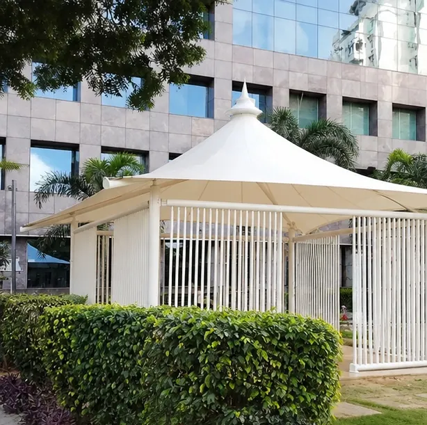
- ProjectDhoot Infrastructure, Gurgaon
- ArrangementSingle-point foundations
- WhyColumns concentrated to keep the area beneath clear
Where the ground area has to stay usable, the structure is arranged so that each support lands on one point rather than spreading across the space. The foundation takes more load, and the site keeps its floor.
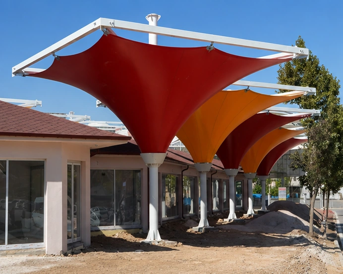
- ProjectTata, Panchkula
- ArrangementOne column, one foundation
- WhyAn inverted umbrella concentrates the whole roof into a single base
The extreme case: one support for the entire structure. Everything the wind does to that roof arrives at one footing, which is sized accordingly.
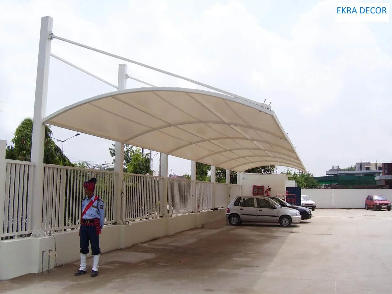
The third is the hero photograph at the top of this page — the car park canopy at Manesar, where a deliberately light structure allowed correspondingly small footings across a large number of bays. See the project →
What a foundation design has to contain
Ask for these before work starts. They are the difference between a structure that has been engineered and a shape that has been priced.
The design wind speed
And the code it was taken from. IS 875 Part 3, for your location, adjusted for terrain and height.
The footing schedule
Type and size for each support, as a drawing rather than a sentence.
The soil assumption
What bearing capacity the design assumed, and whether it came from a test or an estimate.
The anchor detail
Bolt size, layout and embedment at the base of each column.
Uplift and overturning checks
Stated as checks that were performed, not as a claim that the structure is strong.
Where the water goes
Drainage at the base, so the footing is not standing in it.
All of it belongs in the handover pack, with the design, because a foundation is the one part of the structure nobody can inspect afterwards without destroying it. Our questions before signing piece sets out how to ask for this without an argument.
Where foundations go wrong
Almost every one of these is a decision taken to save time, and visible only years later.
Bolted to existing paving
Paving is not designed to be pulled upward. Anchoring a canopy to a slab nobody checked is the failure people later describe as the roof having blown away.
One size for every site
A footing schedule reused from another job, with no soil assumption behind it for this one.
Sized for weight, not wind
Gravity-sized footings under a roof whose governing case is uplift. They look like adequate concrete and are not.
No drainage at the base
Standing water at the pedestal, corroding the bolts that are doing the holding down.
Drilled on site
Galvanising cut through after it was applied, leaving bare steel at the exact point where load is transferred.
Undocumented
No wind speed, no soil assumption, no footing drawing — nothing anyone can check, now or later.
Tensile Structure Foundation FAQ
Uplift, codes, footing types, soil and what to ask for in writing.
Because the load that governs them is wind trying to lift the roof off, not weight pressing it down. A heavy roof resists uplift with its own mass; a membrane roof weighs almost nothing, so the resistance has to come from the footings instead. The lighter the roof, the harder the foundation has to work.
Footings are designed to IS 456 and checked for uplift and overturning rather than gravity alone. The wind pressure they are sized against comes from IS 875 (Part 3) for the specific site, and the steel frame above them is designed to IS 800.
Pad, raft or pile, depending on the loads and the soil. An isolated pad under each column is the common case; a raft spreads load where the ground is weaker or variable; piles are used in soft or filled ground. Mass anchor blocks are used where stay cables come down to ground.
Not as a foundation, and not without checking. Paving is not designed to be pulled upward, and any existing slab has to be assessed by an engineer against the uplift before anything is anchored to it. A canopy bolted to existing paving because it was quicker is a common cause of later failure.
There is no single answer, and anyone offering one without seeing the site is guessing. Depth and size follow from the design wind pressure for that location and from what the ground can carry, which is why the soil assumption has to be written down alongside the design.
Yes, and significantly. The same canopy needs a different footing in dense clay and in loose fill, because a footing resists uplift partly through the weight of soil sitting on top of it. Two apparently identical plots can need different excavations.
They set the pace on site, but they run in parallel with fabrication rather than after it. Steel and membrane are made in the workshop while the footings are cast, which is what keeps the on-site programme short.
Yes. Re-skinning is a planned event rather than a rebuild — the steel, cables and foundations stay and a new set of membrane panels goes on. It is the largest whole-life cost advantage a tensile roof has over a conventional one.
Let’s Build Your Structure
Speak directly with our structural engineering team to discuss your project dimensions, material options, or to schedule a free on-site technical inspection across India.
- 28+Years experience
- Pan-IndiaTurnkey execution
- ISO9001:2015 certified
Request an itemised price quote
Fill in your requirements below for a free engineering assessment & itemised estimate.
* required — everything else is optional
Your details are used only to respond to this enquiry.
Chat with an Engineer on WhatsApp